


Support for 3D modeling and resource integration
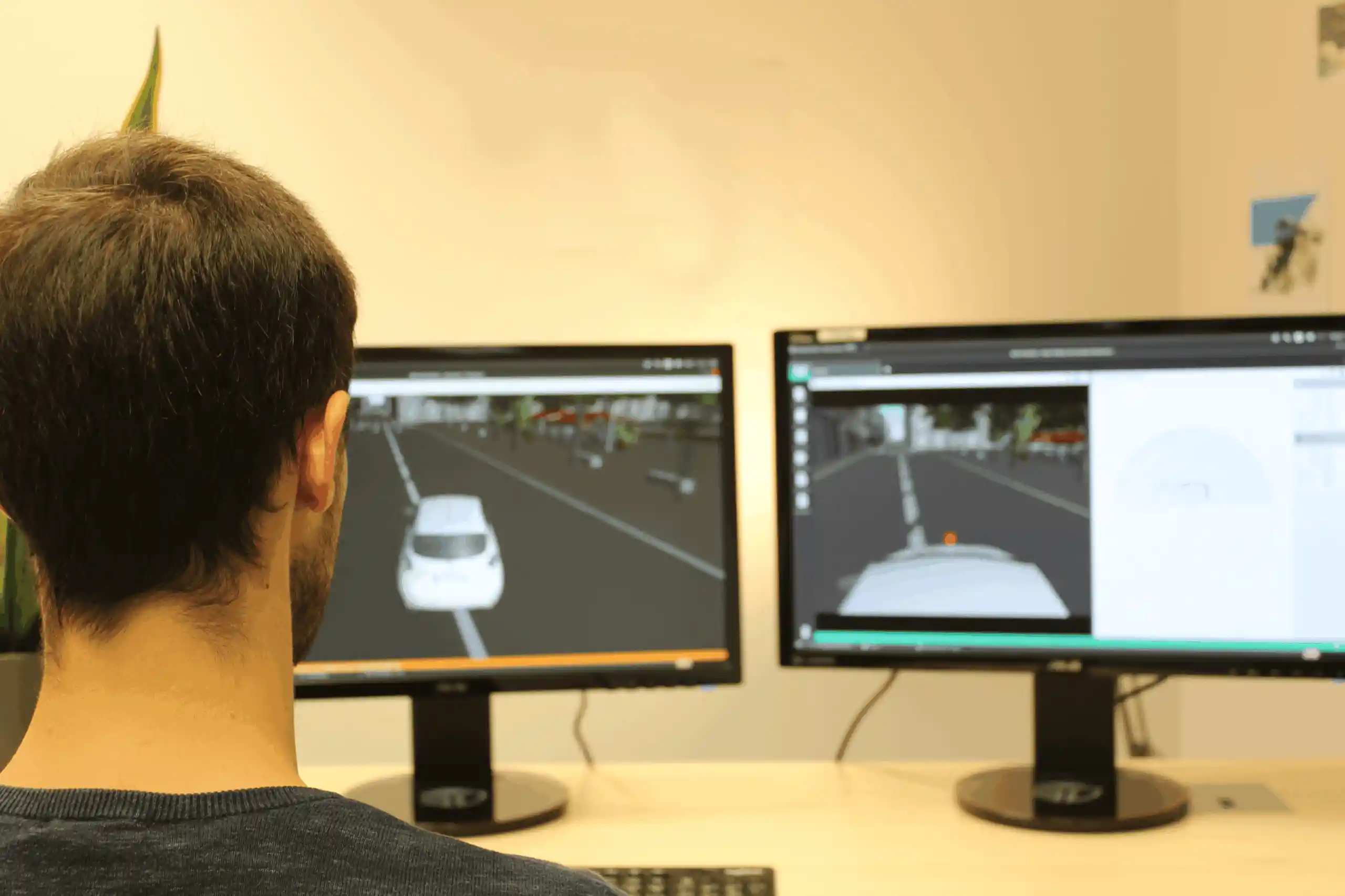
Set up your dynamic systems, sensors, and 3D environments for your simulation scenarios.
Several editing functions are available: defining the visual appearance, the physical geometry of the system, the mechanical behavior, and visual programming.
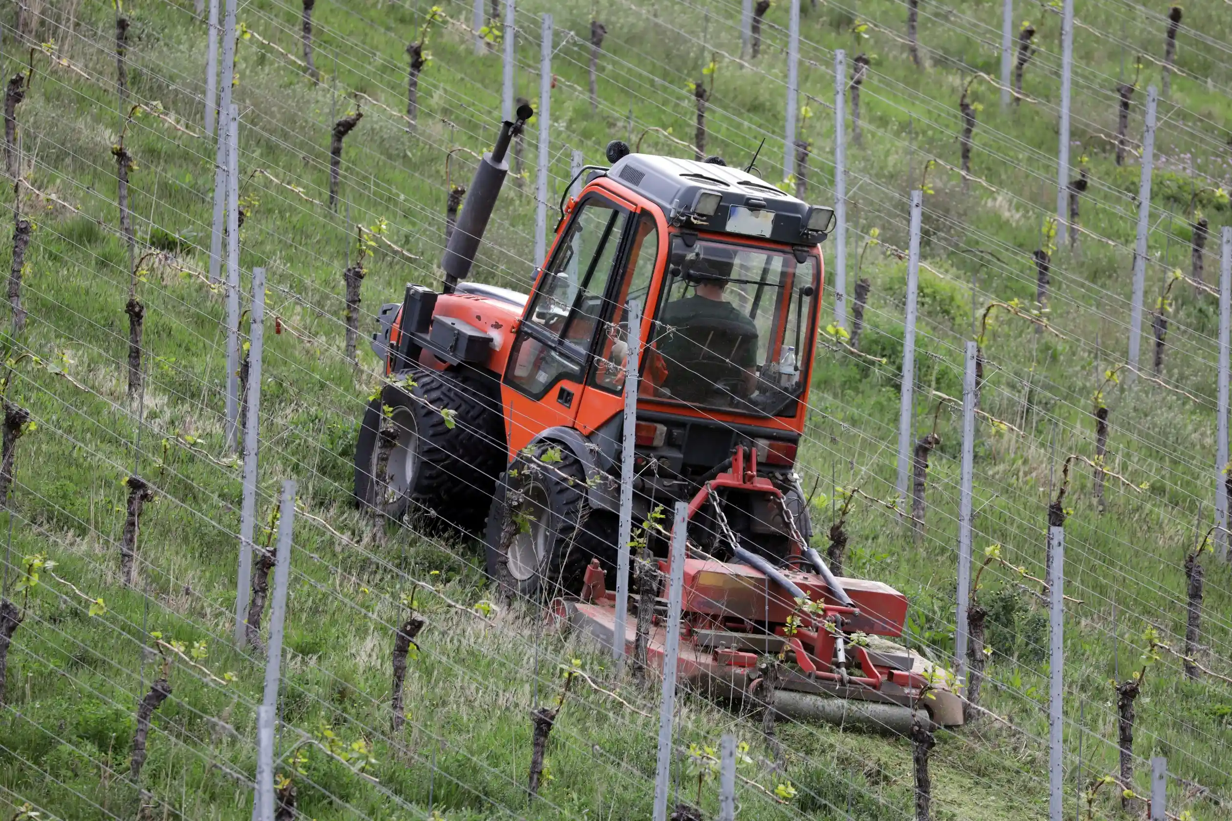
Your 3D models can be in various standard formats created through 3D computer graphics or CAD modeling. This means you can use new models as well as reuse models you already have.
You can finely tune the visual behavior, such as the color of geometric shapes, their visual appearance, and the positioning of controllable point lights (such as vehicle headlights).
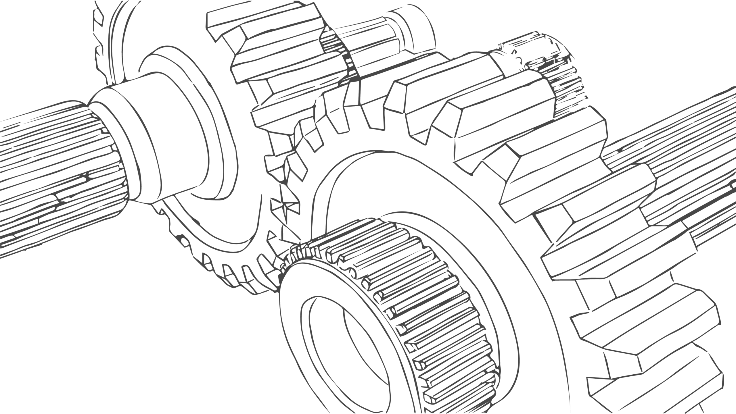
Physical 3D modeling is also user-defined, allowing users to reuse an existing model, which they can adapt, simplify, or create from scratch.
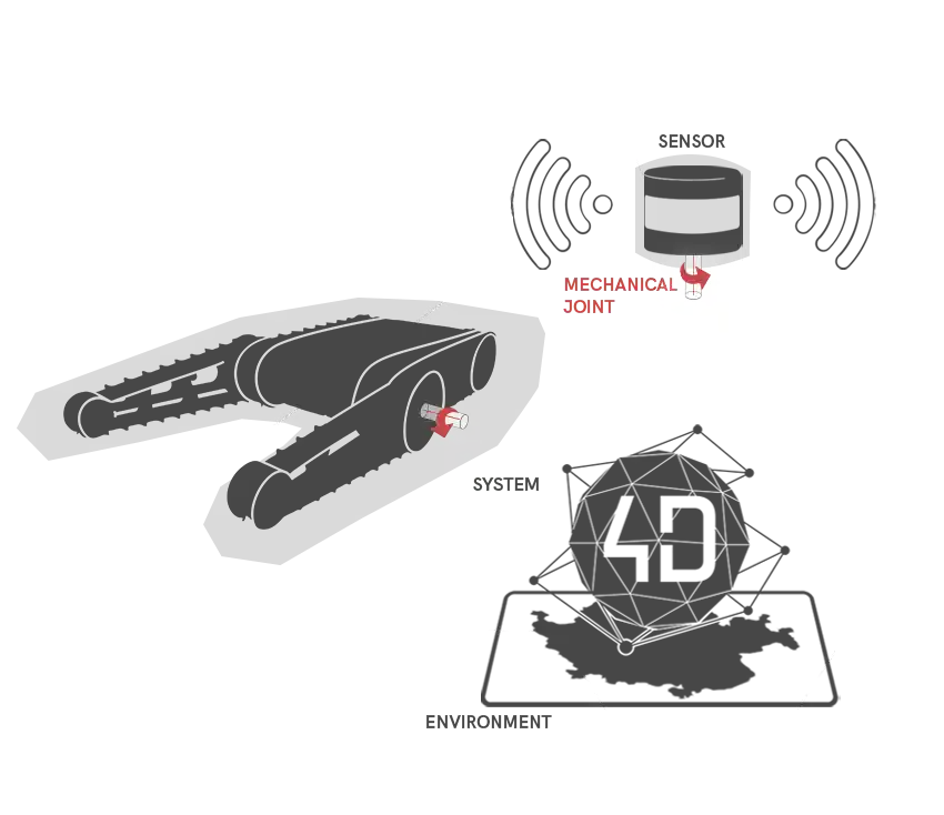
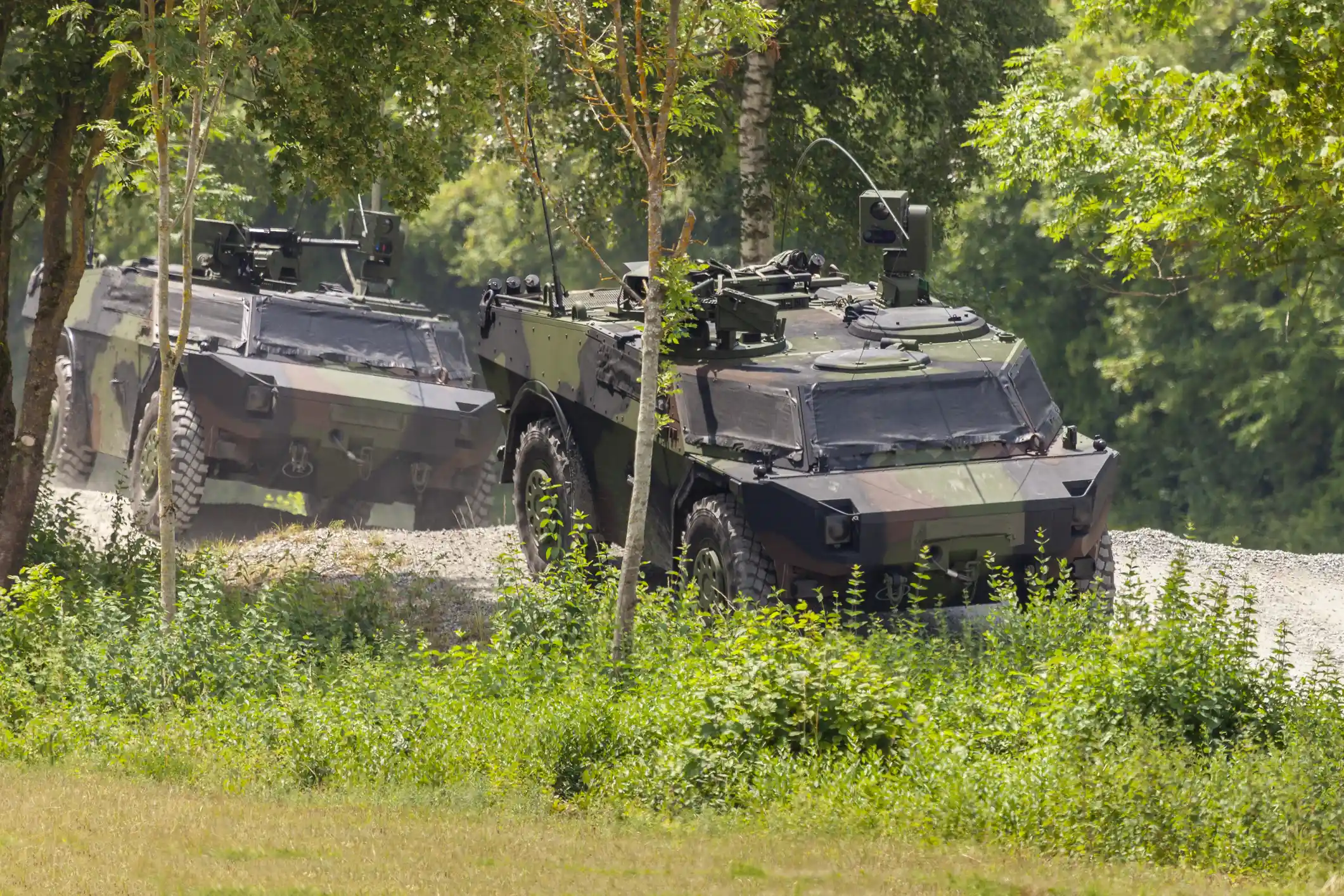
Using the subassemblies you create, 4DV-SYSTEM DESIGNER lets you define the mechanical architecture of your system yourself by specifying all of its components and the mechanical connections that govern them.
It is possible to precisely define the dynamic and physical parameters of resources by characterizing the behavior of each sub-object that makes up the system.
In particular, the following can be defined: the mass and inertial tensor of sub-objects, collision models, and materials relevant to interactions such as contact or distance sensor responses, etc.
Schedule the operating mode for your resources
The internal logic of the resources can be configured using logic blocks provided in the software (internal control loop, basic mathematical functions, logic blocks associated with sensor data).
The use of these logic blocks enhances the level of modeling of system behavior, particularly through the definition of control laws, sensor data processing, and so on.
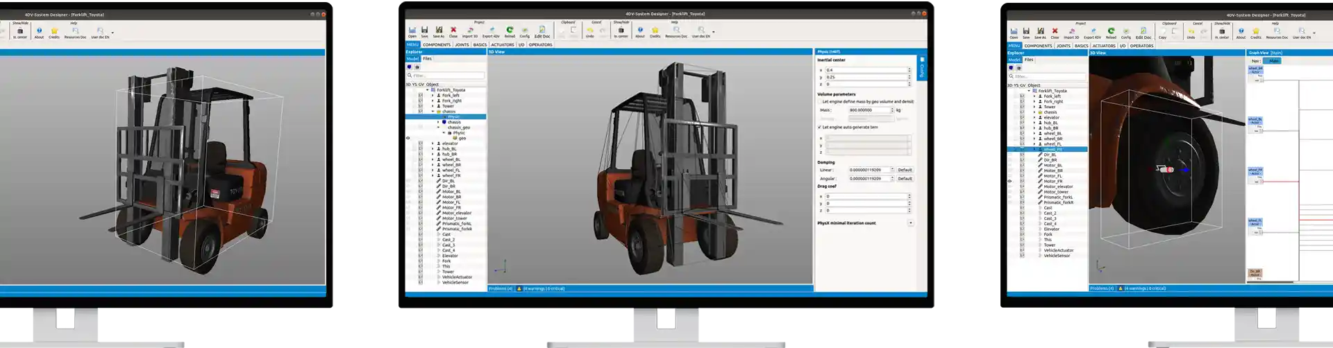
4DV-SYSTEM DESIGNER User Interface
For greater user convenience, resources are prepared in 4DV-SYSTEM DESIGNER using an interface whose user experience is similar to that of the 4DV-EDITOR work environment.
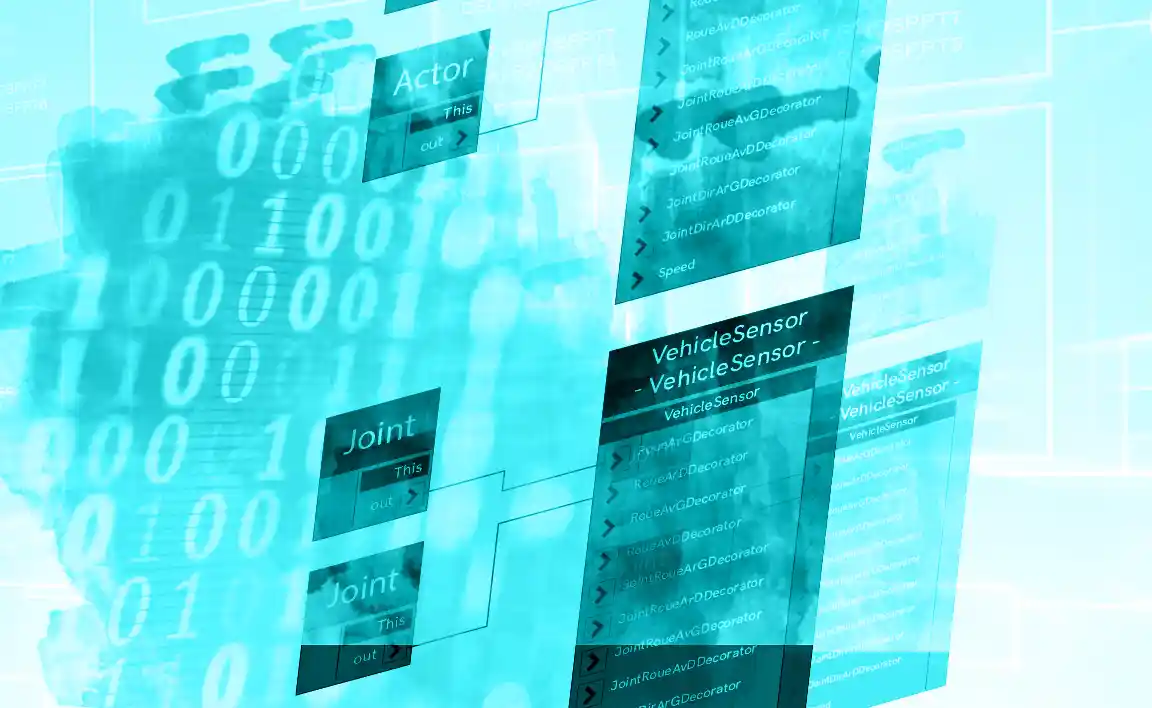
The 4DV-SYSTEM DESIGNER interface is organized around the use of several views: a tree view for exploring and organizing system components, a 3D view for visualizing component positions, a logic block diagram view for interconnecting components to visually program their dynamic behavior, a view for defining component coordinates and physical characteristics, and finally a view for controlling system settings.
This makes it possible to focus on advanced resource configuration.